

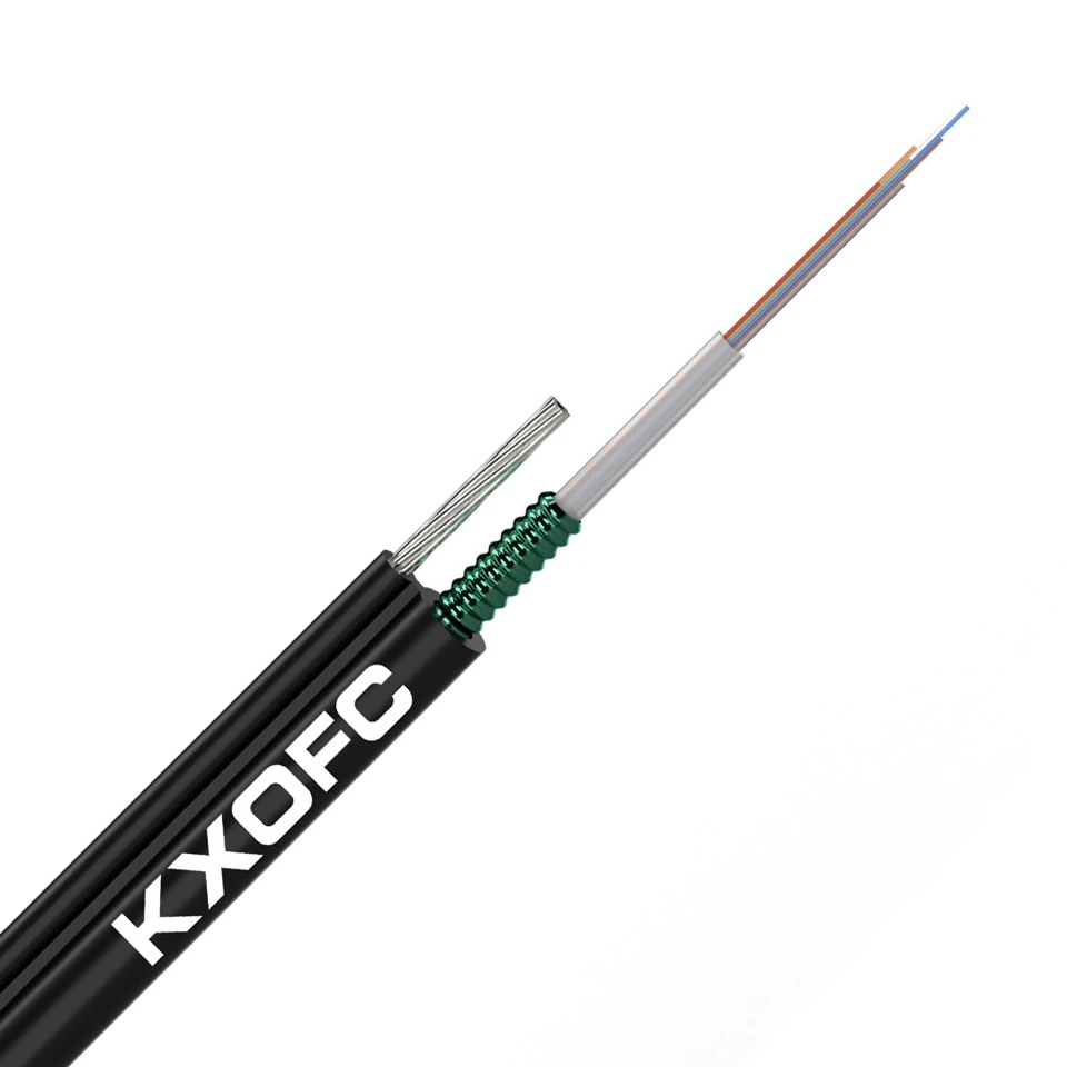
Fig 8 Cable
GYXTC8S Figure 8 fiber optic cable efficiently transmits optical signals, aerial self-supporting armored Figure 8 Cables stably carries large-capacity data, and ensures continuous and uninterrupted communication signals. With its strong protective performance featuring steel strips and figure-8 structure suitable for overhead installation, fiber figure 8 efficiently connects various communication nodes.
Description
Technical Parameters
our company
Features
- Armored reinforcement for excellent impact resistance.
- Efficient transmission enabling operation with large-capacity data.
- Good corrosion resistance, adaptable to various harsh environments.
- Easy installation ensuring guaranteed construction efficiency.
Environmental Characteristics
• Transport/storage temperature: -40℃ to +60℃
Delivery Length
• Standard reel length: 2km/drum; other lengths are also available.
Can we print our own logo and cable marking?
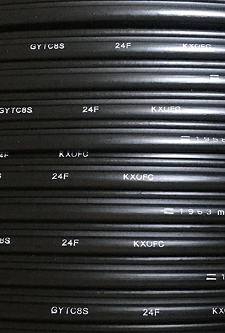
Absolutely. We can print your company logo, brand name, meter mark, batch number and specification information on the cable sheath for free.
own brand




Pack and ship


Tips
Hardly-defined regulations for the bending radius of optical fibers
Static bending radius (permanent fixed state after completion): ≥ 10 times the overall outer diameter of the optical cable. Meaning: When the line construction is completed and remains stationary for a long time, the minimum radius of all arc bends and the remaining loops of coiling cannot be lower than 10 times the thickness of the optical cable.
Dynamic bending radius (construction pulling, temporary bending during pipe installation): Hard standard ≥ 20 times the overall outer diameter of the optical cable. Meaning: During processes such as pipe insertion, dragging, temporary storage, and transportation and pulling, the optical cable will continuously be subjected to force and deformation. For temporary bending, a margin of at least one times the original should be provided to prevent the fiber core from being damaged instantly during dragging. For an optical cable with an outer diameter of 10mm, during construction dragging, the minimum temporary bending radius must reach 200mm. It is strictly prohibited to forcibly squeeze and narrow the arc at the pipe corner during pipe insertion.
Optical fibers lock the optical signals through the difference in refractive indices between the core and the cladding. The light is completely confined within the core and transmitted forward. When the bending radius is too small and close to a dead fold, mode leakage occurs: the optical cable is severely bent, causing a significant deviation in the optical path within the core; the light signal originally enclosed within the core breaks through the cladding and scatters and dissipates outward; a large amount of light signals leak from the bending point, directly causing a significant increase in line attenuation; long-term tight bending with a small radius causes microscopic cracks inside the glass core, and the longer the time, the more severe the loss, eventually resulting in complete loss of light. Key reminder: These micro-cracks are completely invisible to the naked eye. The current fusion splicing and light transmission tests are completely normal. However, after temperature changes, vibrations, and rainwater immersion, the hidden dangers suddenly emerge and are extremely difficult to locate and troubleshoot.
On-site construction layout plan, easily meeting the bending radius standards
1. Cable routing: Special large-radius curved pipes are used to replace the right-angle elbows of PVC and PE cable conduits for bends. All large-radius curved pipes or extended pipes are selected to avoid direct 90-degree straight connections; Buffer arcs are reserved for the entrances and exits of weak current boxes and waterproof boxes, and they are not directly pressed against the box bodies in a hard fold.
2. Cable trays/line slots turning: Arc transition accessories are installed at the turning positions of metal cable trays and plastic line slots. Matching arc transition fittings are provided to ensure that the internal cable routing meets the arc radius standards; Multiple layers of cables are arranged separately, without squeezing or stacking, to avoid the lower-level optical cables being severely compressed and having small bending radii.
3. Reserve excess cables: The remaining cables reserved for the machine room, weak current well, and outdoor waterproof box are uniformly wound into large circular rings with a diameter of more than 20 cm. Soft binding tapes are loosely fixed, and multiple layers of overlapping and squeezing are prohibited.
4. Outdoor overhead and exterior line drop water bends standard: For outdoor cables entering and exiting walls, equipment boxes, etc., a gentle drip water bend is made downward. The arc radius is not less than 10 times the outer diameter of the optical cable, which not only prevents water leakage but also avoids small-angle bending.
5. Binding and fixing: Only use soft binding tapes. Select sponge-coated binding tapes, nylon soft binding tapes. After binding, a small amount of movable space is retained. The binding should not be locked, tightened, or compressed to cause the optical cable to deform.
Hot Tags: fig 8 cable, China fig 8 cable manufacturers, suppliers, factory, Aerial Fibre Optic Cable, Figure 8 Fiber Optic Cable, Outdoor Aerial Fiber Optic Cable, Overhead Fiber Optic Cable, Self Supporting Aerial Fiber Cable, Self Supporting Fiber Optic Cable
Technical Characteristics
|
Fiber Count |
2~24 |
|
Loose Diameters |
2.3 mm |
|
Loose Material |
PBT ((Polybutylene Terephthalate)) |
|
Armor |
Steel tape |
|
Self Strength Messenger |
7*1.2mm Steel wire |
|
Nominal Outer Dimensions |
7.0mm *12mm(±0.3) |
|
Outer Jacket Material |
HDPE |
|
Tension Strength (Long-Term /Short-Term) |
1000N/3000N |
|
Crush Resistance (Long-Term /Short-Term) |
300 N/100mm 1000N/100mm |
|
Minimum Bend Radius (Static / Dynamic) |
10 x OD / 20 x OD |
*All above the cable size can be customized.
Previous
Figure 8 CableNext
G652d Optical FiberSend Inquiry


