

Figure 8 Cable
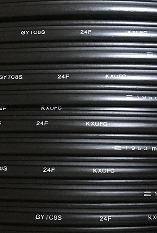
GYFTC8Y fiber optic overhead cable adopts a figure-8 self-supporting structure, fiber optic overhead cable enabling convenient overhead installation without the need for additional suspension wires. Self supporting cable can effectively protect optical fibers from external damage, laying a solid foundation for optical signal transmission. Aerial self-supporting optical fiber cable core features high-efficiency optical signal transmission capability.
Description
Technical Parameters
our company
Features
- Figure-8 cable structure, enabling convenient construction and high efficiency.
- UV resistance, ensuring no cracking during long-term outdoor use.
- Light weight material, reducing overhead load-bearing pressure.
- Low-loss design, minimizing long-distance signal attenuation.
Environmental Characteristics
• Transport/storage temperature: -40℃ to +60℃
Delivery Length
• Standard reel length: 2km/drum; other lengths are also available.
What fiber types do you use?
We mainly use brand new qualified fiber: G652D for long-distance trunk communication, G657A1/A2 for bending-resistant indoor and wiring projects. All fibers have stable transmission performance and low loss.
own brand




Pack and ship


Tip
Emergency Repair Procedure for Optical Cables (Five Steps)
Step 1: Precise breakpoint location (prevent blind excavation)
The slowest and most time-consuming part of the repair is: blindly searching for the breakpoint. The standard operation involves two safety measures:
1. Use the OTDR precise distance measurement equipment to draw a curve, read out the exact breakpoint distance, confirm that it is a complete fiber break, record the data, and lock in the approximate range.
2. Conduct a rapid manual line inspection combined with the excavation location during construction, the direction of the pipe trench, and the new soil marks on the ground, to quickly narrow down the scope. Key experience: The OTDR has a few-meter error margin. Do not stubbornly stick to a specific number. Prioritize looking at the latest damaged, stretched, or crushed points on the site. The core of this step: First determine the breakpoint, then take action. Prevent large-scale random excavation.
Step 2: Prepare all the repair materials at once (without making multiple trips) The most common problem in emergency repairs is running out of tools or consumables halfway through, which delays the crucial restoration time.
Standard Repair Tool Kit List (for direct collection):
1. Equipment: OTDR, fusion splicer, power supply/charging battery, red light pen, optical power meter
2. Consumables: Fiber optic heat shrink tubing, cleaning cotton, alcohol, new short sections of optical cable, cable ties, waterproof tape
3. Accessories: Optical cable junction box (universal models for 2 cores/4 cores/12 cores), sheath tube, waterproof tape
4. Tools: Fiber stripping pliers, cutting knife, utility knife, shovel, gloves, cleaning cloth Tip: Always keep a set of emergency repair kits on hand. There's no need to search for materials temporarily, which significantly speeds up the process.
Step 3: Excavation, exposing the cable, and protective soil removal (most likely to damage the secondary optical fibers) After finding the break point, it is strictly prohibited to dig and pry forcefully! Many optical cables are only broken at one end. Forceful digging and shoveling will cause the intact fibers to be damaged and elongated, expanding the damaged area.
Standard construction procedures:
1. Lightly scrape around the break point, remove the loose soil, and expose sufficient splicing margin
2. Gently pull out both ends of the optical cable, check if there are any hidden damages to the outer sheath, armor, and fibers
3. Reserve sufficient cable splicing length at both ends (reserve 3-5 meters for each end), to avoid the tight tension of the red line after splicing
Guidelines: If there is any slight bruising or cracking of the outer sheath, simply cut off an additional section to eliminate potential hidden risks.
Step 4: Fusion splicing + Double Testing (Ensure One-Time Success) After the cleaning is completed, enter the core repair stage. Follow the formal fusion splicing standards throughout, without cutting corners.
1. Standard fusion splicing process: Fiber stripping → One-way alcohol cleaning → High-precision cutting → Alignment and fusion → Heat shrink protection and acceptance. Values: Single-mode loss ≤ 0.05 dB. It is strictly prohibited to use at 0.1 dB or above as a compromise.
2. Specification of connector box fiber arrangement (The root cause of 90% rework) Many emergency repairs were completed at that time, but the network went down again within half a month. All were caused by the non-standard fiber arrangement: Prohibit right-angle bending, prohibit tight tension, prohibit squeezing and stacking all fiber cores in a large circular arc, neatly arrange layer by layer, without crossing, without twisting, fix the heat shrink connector in the center, without tension, without hanging, the remaining fibers are all stored in the box, the box opening has no wire pressing, no worn surface.
3. Double testing to confirm fusion splicing is completed. First, use a red light pen for on-off testing, then use OTDR to retest the entire curve to confirm no significant loss, no hidden bends, no abnormal reflections, and consider the repair completed.
Step 5: Waterproof sealing + backfill restoration (final touch for life) Emergency repairs do not end once the fusion welding is completed. If the finishing work is not done properly, the cable will definitely leak water and malfunction during the rainy season.
Standard finishing process:
1. Press the joint box rubber strips firmly and tighten the screws diagonally to achieve a complete and watertight seal.
2. Wrap waterproof tape around the inlet and outlet ports to prevent water from seeping in.
3. Backfill the pipe trench with fine soil first and then the original soil. Do not directly compact large pieces of gravel onto the optical cable.
4. Level the ground, mark the lines properly, and avoid secondary excavation that may cause damage to the lines.
Hot Tags: figure 8 cable, China figure 8 cable manufacturers, suppliers, factory, Aerial Fiber Optic Cable, Aerial Fibre Optic Cable, Fiber Optic Overhead Cable, Figure 8 Fiber Optic Cable, Self Supporting Aerial Fiber Cable, Self Supporting Fiber Optic Cable
Technical Characteristics
|
Fiber Count |
12~144 |
|
Loose Diameters |
2.1 mm |
|
Loose Material |
PBT ((Polybutylene Terephthalate)) |
|
Central Strength Member |
FRP |
|
Outer Jacket Material |
HDPE |
|
Self Strength Messenger |
7*1.2mm Steel wires |
|
Nominal Outer Dimension |
9.0mm*12.8mm (±0.3) |
|
Tension Strength (Long-Term /Short-Term) |
3000N/7000N |
|
Crush Resistance (Long-Term /Short-Term) |
300 N/1000mm |
|
Minimum Bend Radius (Static / Dynamic) |
10 x OD / 20 x OD |
*All above the cable size can be customized.
Previous
No InformationNext
Fig 8 CableSend Inquiry


