
outdoor fiber cable
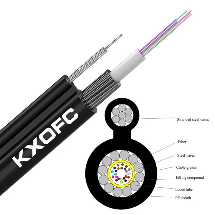
GYXTC8Y outdoor fiber cable is designed for use in aerial outside plant installations. Fibers are housed in loose tubes that made of high-modulus plastic and filled with jelly. The steel wires around the central loose tube to form a cable core.Outdoor fiber cable, PE outer coating, made in the shape of figure 8 , self-support part 7 steel wires (or 1 single steel messenger) woven together.
Description
Technical Parameters
our company
Features
Outdoor aerial fiber optic cable has reasonable design and accurate control of the residual length of the fiber in the loose tube, so that the cable has excellent tensile performance and temperature performance. Outdoor aerial fiber optic cable GYXTC8Y core is filled with oil paste to ensure longitudinal water resistance. A single polyethylene jacket with additives offers superior protection against UV radiation, fungus, abrasion, and other environmental factors.
Environmental Characteristics
• Transport/storage temperature: -40℃ to +60℃
Delivery Length
• Standard reel length: 2km/drum; other lengths are also available.
Design and service
Cable design and package design available. OEM/ODM service also available.
You can share us your requirement.
own brand




Pack and ship


Tips
Design and Application of New Type of Slotted Optical Cable outdoor fiber cable
With the advent of the F5G era, Information and Communication Technology (ICT) is developing rapidly, and physical fiber optic networks are transforming into all-optical service networks. This includes not only all-optical access networks but also all-optical transport networks, providing a superior connectivity experience for various users and laying a solid foundation for industry digital upgrades. All-optical access networks provide superior connectivity for users in various scenarios, including individuals, homes, and enterprises; all-optical transport networks build the foundational infrastructure and extend into service areas, creating a solid foundation for industry digital upgrades with high-quality next-generation optical transport network connections.
Currently, traditional PON networks in China typically use ordinary outdoor optical cables such as GYTA and GYTS for their distribution segments. In high-density fiber access OLT-ONU nodes, multiple laying and splicing processes are required. To meet the demands of higher-density cabling, this paper proposes an innovative snap-fit optical cable design. This solution optimizes the cable's structural design, achieving rapid deployment and low-cost maintenance of the optical distribution network through snap-fit splicing. Compared to traditional optical cables, the new snap-fit cable exhibits significant advantages in high-density access environments, including higher fiber density, smaller outer diameter, and stronger environmental adaptability. It also avoids multiple splicing operations at cable breaks, effectively improving cable laying speed and reducing link loss caused by splicing nodes.
Product Design
The new easy-to-split optical cable designed in this study is divided into two specifications: indoor and outdoor, according to different application scenarios. The structure of the optical cable is shown in Figure 1. The indoor type of optical cable emphasizes flame retardant performance, while the outdoor type focuses on weather resistance and water resistance. According to the combination form of optical units, it can be divided into tight-buffered type and micro-tube type.
The main features of this product include:
The optical unit is composed of tight-buffered optical fiber or oil-filled micro-tube. The tight-buffered structure can be expanded to a maximum of 24 cores, and the micro-tube structure can be expanded to a maximum of 288 cores. Each micro-tube unit contains 24 colored optical fibers. Parallel FRP (Fiber Reinforced Plastics) is used as a reinforcing member to provide tensile strength.
In order to facilitate stripping, the inside of the optical cable is designed as an elliptical structure, and there are stripping marks on the thin wall of the optical cable. A window can be opened at any position along the length of the cable, and the optical unit inside the micro-tube can be easily pulled out without the aid of tools to separate the optical fiber.
Achieving technological innovation of large core count and small size, with a maximum core count of up to 288 cores, high density and large capacity. Compared with ordinary optical cables with the same core count, the outer diameter can be reduced by 20%-30%, effectively improving pipeline resources.outdoor fiber cable
The outer sheath can be selected from polyethylene or low-smoke halogen-free depending on the indoor and outdoor use environment. In indoor applications, high flame retardant, low-smoke halogen-free materials can be selected, which can meet GB 31247-2014 (fire performance classification of cables and optical cables) and EU CPR (Construction Products Regulation) certification. In outdoor applications, its all-dielectric characteristics do not require grounding wires, and the optical cable is lighter and easier to lay.
With the continuous growth of optical transmission information, existing urban pipeline resources are becoming increasingly strained. How to increase the density of optical fibers in a single cable while maintaining or even reducing its outer diameter? The design of the easy-to-split optical cable provides a practical solution. It uses high-density optical unit bundles, with options for 2 to 24 cores per bundle. The maximum outer diameter of the bundle does not exceed 1.5mm. Sufficient space is reserved in the cable for easy bundle removal, and the one-time forming of the cable also improves production efficiency. Figure 2 compares the outer diameter of the easy-to-split optical cable with that of a conventional optical cable. As can be seen from Figure 2, with the same number of cores, the outer diameter of the easy-to-split optical cable can be reduced by 20%-30% compared to the conventional optical cable. Furthermore, the larger the number of cores, the more significant the advantage in outer diameter reduction, greatly improving the utilization rate of pipeline resources.
Depending on the different outdoor and indoor usage scenarios, the new easy-to-split optical cable can be made of different materials and components. For outdoor scenarios, considering the requirements for water resistance and abrasion resistance, it can be designed with water-blocking yarn filling, water-blocking tape wrapping, and PE outer sheath to meet usage needs. Compared with conventional optical cables, all materials are all dielectric, eliminating the need for grounding wires and making cabling construction more efficient. For indoor scenarios, considering the flame retardant requirements, the sheath can use high flame retardant LSZH (low smoke zero halogen, flame retardant polyolefin material), and the material meets the flame retardant requirements for indoor cabling.
In addition, we also conducted tests in actual use. Figure 3 shows the overall scheme for the construction and cabling of the spliced optical cable, that is, a window is opened in the optical cable sheath at each drop point. The optical cable is fixed in the fiber distribution box, and the optical fibers that need to be led out are pulled out and fused with the incoming optical cable or pigtail. The optical fibers that are not led out are not cut in the fiber distribution box and pass straight through. The splicing method can reduce the splice loss of all optical fibers that need to be fused at the optical access point due to the need to cut the optical cable, and effectively improve the construction speed by reducing the number of optical fiber splices. Figure 4 shows the completion of the line deployment after the optical unit is spliced out of the spliced optical cable at the optical access point and fused with the pigtail.outdoor fiber cable
In the real-world pilot testing phase, we calculated the construction costs of ordinary optical cables and easy-splitter optical cables for the same usage scenario. Taking a commercial building with more than 500 households as an example, 300 meters of optical cable need to be laid from the central cabinet (Level 1 optical exchange) to the building. Assuming the building has 33 floors, 8 cabinets are needed, with 5 meters of optical cable laid on each floor and 10 meters of optical cable reserved in each cabinet, for a total of 545 meters of optical cable. The comparison of the total material cost and fiber splicing cost required for the line laying is shown in Table 2. The investment for ordinary optical cables is the cost of the wiring when using conventional GYTA optical cables for laying. The investment for ordinary optical cable splicing is the cost of fiber splicing in each cabinet of the building when using conventional GYTA optical cables for access. The investment for easy-splitter optical cables is the total cost of wiring and access fiber splicing when using easy-splitter optical cables for laying. It can be seen that in large commercial office buildings or high-rise buildings, as the demand for optical fiber access points and optical link lengths increases, the cost advantage of easy-splitter optical cables becomes more and more obvious.
Our easily-connected optical cable features a smaller outer diameter and higher integration for the same core count, and can be customized for different usage environments. This product meets the mechanical and environmental performance requirements of real-world scenarios, fulfills practical engineering needs, and effectively improves construction efficiency while reducing line loss and construction costs. In the future, we will further explore the application of this technology in a wider range of fields and dedicate ourselves to improving its performance to meet the ever-growing network demands.
Bending Radius of Optical Cables
Optical cables inevitably undergo bending during daily use, transportation, installation, and maintenance. Some bends are permanent, while others are temporary. What are the prerequisites for these bending operations? The key is to ensure that the optical and mechanical properties of the optical cable are not permanently damaged when subjected to bending, and that there is no fatigue damage accumulation or increased attenuation within the designed service life.
In practical applications, the types of bending experienced by optical cables are often categorized into two types: static bending and dynamic bending.
Static Bending (Long-Term Fixed)
Definition: After the optical cable is laid and installed, it remains stationary for a long period, without reciprocating motion, periodic bending, or continuous tension-relaxation cycles, and only bears its own weight and stable clamping force in a stable bending state.
Essence: Single-stage forming, constant stress, no fatigue accumulation.
Typical Scenarios: Duct/cable tray/shaft fixing, ODF fiber coiling, optical distribution box termination, direct-buried optical cables.
Dynamic Bending (Motion/Laying/Cycle)
Definition: The state in which the optical cable is in reciprocating motion, continuous dragging, repeated bending, stretching-relaxation cycle, or under tension bending during installation and traction.
Essence: Alternating stress, fatigue accumulation, and susceptibility to structural damage and degradation.
Typical Scenarios: Cable carrier/robot/elevator following, vehicle-mounted movement, laying traction, and repeated bending tests.
The current standard specifies the minimum allowable bending radius for optical cables: According to the communication industry standard YD/T901-2018, the minimum allowable bending radius for optical cables is expressed as a multiple of the outer diameter D of the optical cable, and it should comply with the provisions of Table 1 below. For indoor flat optical cables, according to industry standard YD/T1258.4-2019, the minimum bending radius should be expressed as a multiple of the flat optical cable height H, while the specific multiple remains unchanged. The flat optical cable should be bent in the flat direction. Specific regulations are as follows:
The bending radius for repeated bending tests of optical cables is determined according to the national standard GB/T7424.21-2021. Unless otherwise specified in the detailed product specifications, the bending radius shall not exceed 20 times the diameter of the optical cable or the minimum mandrel radius, whichever is greater. The minimum mandrel radius for outdoor optical cables is 75mm; for indoor optical cables, it is 75mm or 25mm, to be agreed upon by the user and the supplier. The current YD/T901-2018 references the provisions of GB/T7424.21-2008, which does not explicitly specify the bending radius for bending tests, clarifying that it should be specified in the detailed standard. Therefore, YD/T901-2018 specifies the minimum bending radius for various cable types, and the selection of the bending radius for repeated bending tests should not exceed the dynamic bending radius specified in Table 1 above.
Artificial intelligence (AI) technology is profoundly changing the development landscape of the optical communication industry. This article systematically reviews the current application status and development trends of AI technology from three key aspects: fiber optic design, cable manufacturing, and performance testing. In the field of fiber optic design, AI-assisted reverse engineering methods have significantly shortened the R&D cycle of new optical fibers, making performance optimization of cutting-edge products such as hollow-core and multi-core optical fibers more efficient. In cable manufacturing, AI-powered visual inspection, intelligent process control, and predictive maintenance technologies have significantly improved production efficiency and product quality consistency. In performance testing, AI-enabled automated testing systems are replacing traditional manual interpretation methods, demonstrating significant advantages in fault diagnosis, parameter measurement, and lifespan assessment. AI technology is driving the paradigm shift in optical communication products from "experience-driven" to "data-driven," but it also faces challenges such as insufficient data accumulation, lack of model interpretability, and limited cross-scenario adaptability.
Optical communication is the neural network of modern information society, carrying the vast majority of global data traffic. In recent years, with the explosive growth of cloud computing, big data, and artificial intelligence technologies, the demand for communication bandwidth and transmission speed has continued to rise. Against this industrial backdrop, optical communication products face unprecedented technological challenges.
Traditional fiber optic design methods rely on engineers' experience and repeated numerical simulations; developing a new fiber often takes years. During fiber optic cable manufacturing, product quality consistency highly depends on the skill level and responsibility of operators. Furthermore, in performance testing, a significant amount of work still requires manual operation and subjective judgment, resulting in significant limitations in testing efficiency and accuracy.
The rapid rise of AI technology has brought new possibilities for overcoming these challenges. Deep learning algorithms can automatically learn complex patterns from massive amounts of data, computer vision technology can achieve more precise defect identification than the human eye, and generative models can even proactively "create" better design solutions. These technologies are gradually permeating all aspects of optical communication product design, manufacturing, and testing, driving the entire industry to transform from a traditional "experience-driven" model to a "data-driven" intelligent model. This article will introduce the application progress of AI technology from three dimensions: fiber optic design, cable manufacturing, and performance testing, analyze the changes and value it brings, and look forward to future development trends.
1. Limitations of Traditional Fiber Optic Design
Fiber optics are the most fundamental component in optical communication products. What appears to be a simple fiber actually has a remarkably intricate internal structure. Taking the most commonly used single-mode fiber as an example, the core diameter is only 8 to 10 micrometers, roughly one-tenth the thickness of a human hair. The refractive index distribution between the core and cladding needs precise control; any minute deviation will affect the signal transmission quality.
The traditional fiber optic design process is roughly as follows: First, design engineers propose an initial structural scheme based on experience, including parameters such as core size, refractive index distribution shape, and material selection for each layer. Then, these parameters are input into numerical simulation software, using Maxwell's equations to calculate performance indicators such as mode field distribution, dispersion characteristics, and nonlinear effects. If the simulation results are unsatisfactory, the parameters are manually adjusted, and the calculation is repeated. This process requires iterative iterations, and each simulation can take hours or even days. For new special fibers such as multi-core fibers, few-mode fibers, and photonic crystal fibers, the structural parameters are even more complex, and the design space grows exponentially, often proving inadequate with traditional methods.
2. AI-Assisted Reverse Engineering of Optical Fibers
AI technology has brought entirely new ideas to optical fiber design, the most representative of which is the "reverse engineering" method.
Traditional design is "forward": first, structural parameters are determined, then performance indicators are calculated. Reverse engineering is the opposite: the designer first determines the desired performance target, and then the AI model directly provides the structural parameters that can achieve that target.
The key to achieving reverse engineering lies in training a high-performance neural network model. Researchers first use traditional simulation software to generate massive amounts of "structure-performance" pairing data-that is, randomly generating a large number of optical fiber structural parameters, calculating the corresponding performance indicators, and forming a database. Then, this database is used to train a deep learning model, allowing the model to learn the mapping relationship between structural parameters and performance indicators. After training, the model is "reverse-engineered," inputting the target performance and outputting the optimal structural parameters.
The efficiency improvement of this method is remarkable. Design iteration processes that previously required weeks or even months can be shortened to hours with the help of AI models. More importantly, AI models can sometimes "discover" non-intuitive structural solutions that human designers have never considered.
3. Intelligent Development of New Optical Fibers
Driven by AI technology, the research and development of various new optical fibers has accelerated significantly. Hollow-core optical fiber is one of the most promising areas of research in recent years. This type of fiber has a hollow core, allowing light signals to propagate in air rather than glass. Theoretically, this could overcome the loss limits of traditional optical fibers and increase transmission speeds to near the speed of light in a vacuum. The internal microstructure of hollow-core optical fiber is extremely complex, containing dozens of layers of precise air-hole arrays, making its design optimization urgently requiring AI assistance. Deep learning models can quickly evaluate the performance of different combinations of microstructure parameters, helping engineers find optimal solutions within a vast design space.
Multi-core optical fibers represent another technological route for increasing optical fiber transmission capacity. Integrating multiple cores into a single fiber, each core independently transmits signals, effectively turning one fiber into multiple fibers. The design challenge of multi-core optical fibers lies in suppressing crosstalk between different cores, which involves the coordinated optimization of multiple parameters such as core spacing and refractive index distribution. AI models can simultaneously consider the coupling relationships of multiple performance indicators, achieving overall optimal design for multiple objectives.outdoor fiber cable
Product standards for these new optical fibers are also continuously being improved. Taking hollow-core optical fiber as an example, the China Communications Standards Association (CCSA) is organizing the formulation of relevant industry standards, with many leading companies and research institutions actively participating. AI technology can not only accelerate product development, but also is expected to serve the development and verification of standardized testing methods in the future.
Hot Tags: outdoor fiber cable, China outdoor fiber cable manufacturers, suppliers, factory, Aerial Fibre Optic Cable, Fiber Optic Overhead Cable, fig 8 self support optical fiber cable, Figure 8 Fiber Optic Cable, Outdoor Aerial Fiber Optic Cable, Self Supporting Fiber Optic Cable
Technical Characteristics
|
Fiber Count |
2~12 |
|
Loose Diameters |
2.2 mm |
|
Loose Material |
PBT ((Polybutylene Terephthalate)) |
|
Self Strength Member |
Steel wire |
|
Surrounded steel wires |
12x1.0mm,Plastic coated |
|
Outer Jacket Material |
HDPE |
|
Messenger |
7*1.2mm steel wires |
|
Nominal Outer Dimensions |
8.0mm*13.5mm(±0.3) |
|
Tension Strength (Long-Term /Short-Term) |
3000N/7000N |
|
Crush Resistance (Long-Term /Short-Term) |
300 N/1000mm |
|
Minimum Bend Radius (Static / Dynamic) |
10 x OD / 20 x OD |
*All above the cable size can be customized.
Previous
Outdoor FiberNext
Aerial CableSend Inquiry


