
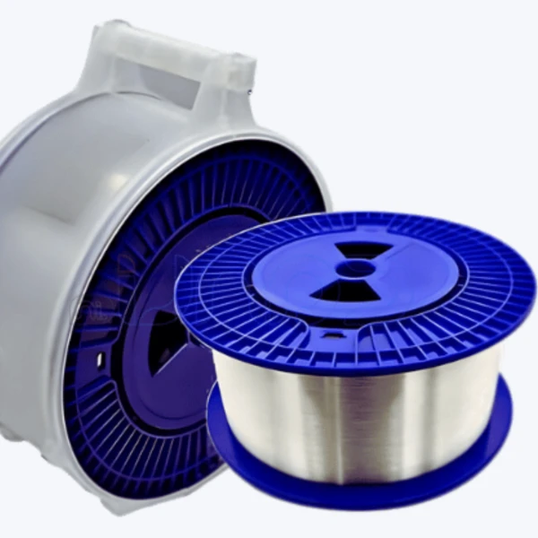
Multi-mode Fiber 50/125 Om3
Description
Technical Parameters
our company

Fiber Muti-mode Application
To determine the appropriate fiber for a high-performance network, it's essential to understand the differences between single-mode and multimode fiber. Multimode fiber has a core diameter of approximately 50 to 62.5 micrometers, allowing multiple optical modes to pass simultaneously. Single-mode fiber, on the other hand, typically has a core diameter between 8 and 10 micrometers, thus allowing only a single optical mode to pass. The ability to allow multiple optical modes through the core gives multimode fiber an advantage in short-distance transmissions, such as interconnects between local area networks (LANs) and connections within data centers. Single-mode fiber, however, excels in long-distance connections within metropolitan area networks (MANs) due to its lower modal dispersion, enabling the transmission of more data over a wider bandwidth, making it more advanced than multimode fiber. Ultimately, the choice between single-mode and multimode fiber depends on the specific needs of the network.

Characteristics
Determining the type of optical fiber (single-mode or multimode) is crucial, as it affects data transmission distance and bandwidth. The core size and cladding diameter also significantly impact integration with existing systems and connectors. Furthermore, checking the required tensile strength and minimum bending radius ensures the spool can withstand the stresses of installation and operation without damage. Finally, inspecting the spool material is helpful, as it relates to the fiber optic spool's lifespan, especially in harsh weather conditions. This, in turn, ensures that all materials and components of the fiber optic system receive comprehensive and ongoing maintenance.
|
Characteristics of OM3 |
Conditions |
Specified values |
Units |
|
Geometry Characteristics |
|||
|
Core Diameter |
-- |
50±2.5 |
[μm] |
|
Core Non-Circularity |
-- |
≤5.0 |
[%] |
|
Cladding Diameter |
-- |
125.0±1.0 |
[μm] |
|
Cladding Non-Circularity |
-- |
≤0.6 |
[%] |
|
Coating Diameter |
-- |
245±7 |
[μm] |
|
Coating/Cladding Concentricity Error |
-- |
≤10.0 |
[μm] |
|
Coating Non-Circularity |
-- |
≤6.0 |
[%] |
|
Core/Cladding Concentricity Error |
-- |
≤1.0 |
[μm] |
|
Delivery Length |
-- |
up to 8.8 |
[km/reel] |
|
Optical Characteristics |
|||
|
Attenuation |
850nm |
≤2.4 |
[dB/km] |
|
1300nm |
≤0.6 |
[dB/km] |
|
|
-- |
-- |
MaxBand® OM2+/OM3/OM4 Bend Insensitive |
|
|
Overfilled Modal Bandwidth |
850nm |
≥700/≥1500/≥3500 |
[MHz·km] |
|
1300nm |
≥500/≥500/≥500 |
[MHz·km] |
|
|
Effective Modal Bandwidth |
850nm |
≥950/≥2000/≥4700 |
[MHz·km] |
|
Application support distance on |
-- |
-- |
-- |
|
40GBASE-SR4 / 100GBASE-SR101 |
850nm |
-/140/170 |
[m] |
|
10GBASE-SR |
850nm |
150/300/550 |
[m] |
|
1000BASE-SR |
850nm |
750/1000/1100 |
[m] |
|
DMD Specification |
Compliant with and more stringent than the requirements of IEC60793-2-10 |
-- |
|
|
Numerical Aperture |
-- |
0.200±0.015 |
-- |
|
Group Refractive Index |
850nm |
1.482 |
-- |
|
1300nm |
1.477 |
-- |
|
|
Zero Dispersion Wavelength(λ0) |
-- |
1295-1340 |
[nm] |
|
Zero Dispersion Slope(S0) |
1295nm≤λ0≤1310nm |
≤0.105 |
[ps/(nm2·km)] |
|
1310nm≤λ0≤1340nm |
≤0.000375(1590-λ0) |
[ps/(nm2·km)] |
|
|
Macrobending Loss2 |
-- |
-- |
-- |
|
2 Turns @ 15 mm Radius |
850nm |
≤0.1 |
[dB] |
|
1300nm |
≤0.3 |
[dB] |
|
|
2 Turns @ 7.5 mm Radius |
850nm |
≤0.2 |
[dB] |
|
1300nm |
≤0.5 |
[dB] |
|
|
Backscatter Characteristics |
1300nm |
|
|
|
Step(Mean of Bidirectional Measurement) |
-- |
≤0.10 |
[dB] |
|
Irregularities Over Fibre Length and Point Discontinuity |
-- |
≤0.10 |
[dB] |
|
Attenuation Uniformity |
-- |
≤0.08 |
[dB/km] |
|
Environmental Characteristics |
850nm & 1300nm |
|
|
|
Temperature Cycling |
-60℃ to 85℃ |
≤0.10 |
[dB/km] |
|
Temperature-Humidity Cycling |
-10℃ to 85℃,4% to 98% RH |
≤0.10 |
[dB/km] |
|
Water Immersion |
23℃, 30 days |
≤0.10 |
[dB/km] |
|
Dry Heat |
85℃,30 days |
≤0.10 |
[dB/km] |
|
Damp Heat |
85℃, 85% RH,30 days |
≤0.10 |
[dB/km] |
|
Mechanical Specification |
|||
|
Proof Test |
-- |
≥9.0 |
[N] |
|
-- |
≥1.0 |
[%] |
|
|
-- |
≥100 |
[kpsi] |
|
|
Coating Strip Force |
typical average force |
1.5 |
[N] |
|
peak force |
≥1.3, ≤8.9 |
[N] |
|
|
Dynamic Stress Corrosion Susceptibility Parameter(nd, typical) |
-- |
20 |
-- |
Multi-mode Fiber 50/125 Om3
'lt is awesome to work with Creative. amazingy organized,easy to communicate with. responsive with next iterations,and beautiful work.
What are fiber optic reels? Why are they important?
Fiber optic reels are essential for fiber optic networks. They support and organize fiber optic cables, preventing damage and simplifying installation, especially with multiple fiber pairs. Maintaining the correct bend radius is also crucial for optimal data transmission in high-speed networks and data centers.
What types of fiber optic reels are available?
Fiber optic reels have various uses, allowing the use of different types of fiber optic cables. Some of the most common reels are for single-mode and multimode fiber, armored fiber optic cables, and bend-resistant fiber optic cables. Reels can also be used for different types of wires, such as patch cords, branch fiber optic cables, and MTP/MPO cables.
How do I choose the right fiber optic reel for my needs?
To choose the right fiber optic reel, consider your fiber type, such as single-mode, OM3, or bend-resistant fiber. Also consider the cable diameter, required length, and the environment in which it will be used, such as in a ventilation duct or riser. Consider its specific application, such as a data center or high-performance network. Consult a fiber optic engineer if you need further advice.
How important is the bend radius of fiber optic spools?
The bend radius is a critical factor in optical fiber because it determines signal integrity. Fiber optic spools are designed to maintain the correct bend radius, ensuring fiber safety and preventing breakage due to excessive bending. Using bend-insensitive fiber optic cables and spools with sufficient radius specifications prevents excessive fiber bending and ensures high-speed data transmission.
Hot Tags: multi-mode fiber 50/125 om3, China multi-mode fiber 50/125 om3 manufacturers, suppliers, factory, Fiber G657A2, fiber optic cable, moisture blocking fiber optic cable, nonmetallic fiber optic cable, OM3 fiber optic cable, optical fiber
Previous
Multi-mode FiberNext
Optic FiberSend Inquiry
You Might Also Like


